


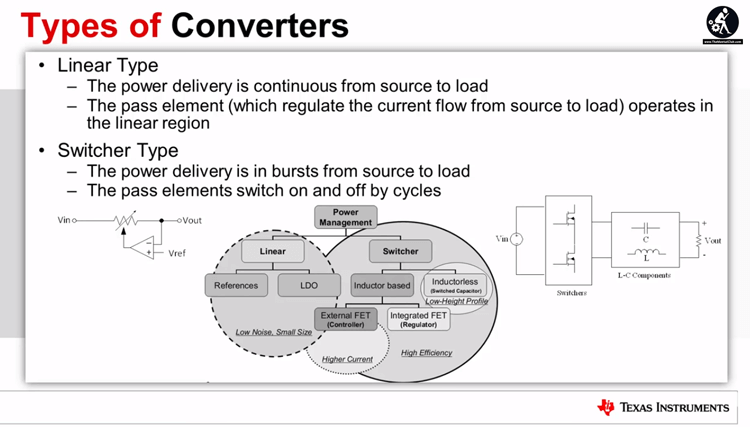
What is topology? It is the connection method of the power devices and the electromagnetic components in the circuit, and the design of the magnetic components, closed-loop compensation circuits, and all the other circuit component designs depend on topology. The most basic topologies are Buck, Boost and Buck/Boost, single-ended flyback (isolation flyback), forward, push-pull, half-bridge and full-bridge variant. Several common switched-mode power supply topology and their applications are introduced in the following.
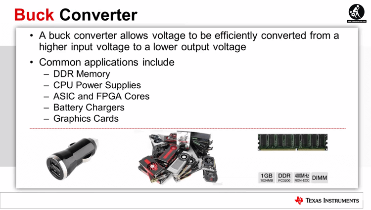
1. Buck Circuit
The buck circuit is a buck converter, which is mainly used in the field of low voltage and large current to solve the problem of conduction loss of the freewheel. The general diode is used for freewheeling, which has a large on-resistance, and the loss is great when applied to a large current. However, if we replace the diode with a MOS transistor with a very small on-resistance the loss problem can be solved, but at the same time, there will be a higher requirement for the drive circuit.
After applying the synchronous rectification technology to the Buck circuit and replacing the diode with the MOS tube, the circuit topologically integrates the Buck converters and Boost converters, which provides a possibility for bi-directional DC/DC conversion. And In the case where one-way buck-boost is needed and the energy can flow in double directions, it has great application value. For example, when the bulk circuit is applied to a hybrid electric vehicle, supplement it with a three-phase controllable full-bridge circuit, which can realize charging and discharging of the battery.

2.Flyback Converter
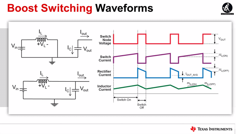
(1) Boost Circuit
In practical applications, the design of the boost circuit is often involved. For large power output, such as DC/DC boost circuit of 70W or above, it is difficult to achieve high power boost conversion due to the limitation of the internal switching tube of the dedicated boost chip. And the high price of the chip makes itself greatly limited in practical applications.
Considering that there are wealth choices for external switch tubes of the boost structure. A DC/DC boost circuit with high power output can be designed by selecting a suitable control chip.
(2) Buck/Boost Converter
The basic non-isolated and isolated Buck/Boost converters are widely used in small and medium power DC/DC converters for their advantages of simple circuit topology, high input voltage range, elevating voltage, and high reliability during load short-circuit.
3. Forward Converter
The double-ended forward converter overcomes the shortcomings of high switching voltage stress in the forward converter, and each switching tube only needs to withstand the input DC voltage, and a reliable magnetic reset of the transformer can be ensured without using a special magnetic reset circuit.
Each of its bridge arms is composed of a diode in series with a switching tube, an there is no danger of straight-through of the bridge arm. Therefore, the double-ended forward converters have their unique advantages and have become one of the most widely used topologies in medium and large power converters.
4. Push-pull Converter
The push-pull converter is the earliest topology application among all the converters and is still widely used in DC/DC converters and DC/AC inverters. Its output can be higher or lower than the input DC voltage. The main output of the closed-loop can maintain stability when the power grid and load change. And the output can be used to well adjusted the grid changes.
5. Half-Bridge Power Circuit
The primary winding voltage of the half-bridge converter is only half of the input voltage. If it has the same output power and twice the primary current as of the push-pull, a larger rated current is required.
The half-bridge converter is suitable for applications with high input voltage and medium output power since the rated voltage on the power tube is ideally the input DC voltage.
6. Full Bridge Power Circuit
Full-bridge power converters are suitable for high-power and high-voltage applications. It has been pointed out that the highest voltage that the power transistor operating in the half-bridge power conversion circuit can withstand is reduced by 1/2 compared to the transistor operating in the push-pull conversion circuit. However, if the output power is required to be the same, the operating current of the transistor will increase.
The full-bridge power conversion circuit is a high-power conversion circuit that can maintain the low voltage withstand of the half-bridge circuit power switching device with the characteristics of the small current-carrying of the push-pull circuit.


 and it may recover your Memory Card")
 – Bangla Typing Software Download")
")


 and it may recover your Memory Card")


Comments are closed.